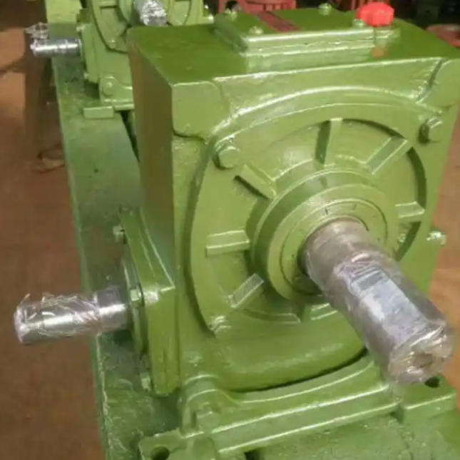
The alignment accuracy of the WHT80-8-I arc cylindrical worm gear reducer is directly related to the stability of equipment operation, bearing life and sealing reliability. Especially under high load conditions such as metallurgy and lifting, small deviations may cause vibration, temperature rise, oil leakage and even gear damage. It must be strictly controlled through scientific methods and professional tools.
1. Key preparations before centering
Cleaning and InspectionClean the oil, rust and burrs on the input/output shaft end and the inner hole of the coupling to ensure that there are no foreign objects on the mating surface that affect the coaxiality.
Tools in placePrepare laser alignment instrument or precision dial indicator (laser recommended, higher accuracy), feeler gauge, torque wrench, level, etc. It is strictly prohibited to rely solely on visual inspection or rough alignment with a ruler.
Preliminary Positioning Lift the reducer into place and pre-tighten the anchor bolts diagonally to keep the base close but leave room for fine adjustment.
2. Precise alignment operation steps
Coupling connection Connect the motor and reducer through an elastic coupling. The elastic element can absorb slight deviations, but high-precision alignment is still required.
Measure radial and axial deviation
Radial deviation ≤ 0.1mm
Axial tilt ≤ 0.2mm/m (For specific values, please refer to the manual of the model, there are slight differences between different brands)
Use a laser alignment instrument or dial indicator to measure the radial runout and end-face parallelism of the two axes at four positions: 0°, 90°, 180°, and 270°.
Calculate the average deviation, ensuring:
Adjust the positionBy increasing or decreasing the motor or reducer base gasket and fine-tuning the moving position, gradually correct the deviation until the standard is reached.
3. Thermal expansion compensation strategy
The operating temperature of the reducer (usually 80–90°C) is higher than that of the motor, and the shaft center will rise when hot. Therefore, compensation should be reserved during cold alignment:
The center of the high-speed shaft of the reducer should be slightly lower than the center of the motor shaft , generally 0.1–0.3mm lower. For specific values, refer to the manufacturer's recommendations.
Avoid 'upper opening' deviation caused by thermal expansion after operation, which will aggravate vibration and bearing load.
4. Key actions after centering
Final tighteningAfter the alignment is up to standard, use a torque wrench to tighten the anchor bolts to the specified torque (such as M16 bolts about 100-120N·m) in a 'cross, step-by-step' method to prevent shell deformation.
Recheck the alignmentMeasure the alignment status again after tightening . Slight deviation may occur due to stress relief. Readjust if necessary.