The WPWD200 worm gear reducer is the 200 mm centre-distance model in WGT Weigao Transmission's universal worm gearbox family. It combines a right-hand single-start worm with an integral motor flange, so the drive motor bolts directly onto the reducer and the whole unit becomes one compact package instead of a motor on a pedestal coupled to a gearbox. That saves the length of a separate bracket, one alignment job and one shaft coupling on the line. With ratios from 1/10 to 1/60 and 623 to 1948 N·m of rated output torque, one casting covers slow augers, ribbon mixers, belt conveyors, hoists and packaging lines. Every figure quoted below is catalogue data for this exact model, so anyone working through gear reducer selection and gearbox sizing can check the numbers directly instead of relying on a family range.
The designation is read left to right. W is the product code for a worm gear speed reducer, P the whole one-piece box structure, the second W the universal box model, and D the input shaft with motor flange; the trailing number is the centre distance in millimetres. The WP family covers 40 mm to 250 mm centre distances, and the model code also allows a two-stage build (E), a multi-stage build (EE), a hollow output shaft (K), and a choice of housing arrangements (A, S, O, X, T, V) that set where the input and output shafts sit. The universal box form lets the same frame be built with different shaft orientations so it can be dropped into a crowded machine layout.
Typical Specifications of the WPWD200 Worm Gear Reducer
| Item | Value | Notes |
| Centre distance | 200 mm | Model number WPWD200 is the centre distance in mm |
| Ratios available | 1/10, 1/15, 1/20, 1/25, 1/30, 1/40, 1/50, 1/60 | Single stage, right-hand worm |
| Rated input power | 11 kW at 1/10 to 1/30; 7.5 kW at 1/40 to 1/60 | Catalogue rating at 1500 r/min input speed |
| Rated output torque | 623 to 1948 N·m | Maximum load the housing allows at each ratio |
| Output speed | 150, 100, 75, 60, 50, 37.5, 30, 25 r/min | At 1500 r/min input |
| Efficiency | 77 to 90 % at 1/10, falling to 60 to 71 % at 1/60 | Ratio dependent; see the table below |
| Input speed range | 600 to 1800 r/min, 2000 r/min maximum | With belt-pulley, coupling or sprocket drive |
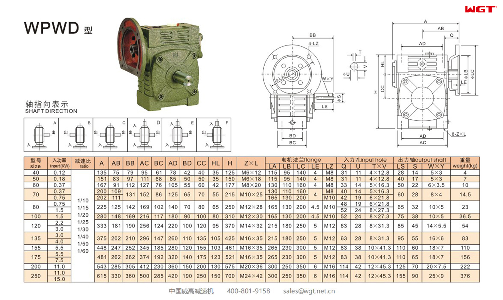
| Overall dimensions | A 543, AB 285, BB 305, AC 412, BC 230, AD 360, BD 150, CC 200, HL 130, H 575 mm | Refer to the dimension drawing for the installation envelope |
| Foot bolts | M20 x 36 | Base plate must be plane, stout and shockproof |
| Motor flange | LA 300, LB 250, LC 350, LE 6 mm, LZ M16 | Bolt circle and pilot diameter for the mounted motor |
| Input bore | Q 114 / U 42 mm, key 12 x 45.3 | Input shaft OD tolerance J6 |
| Output shaft | LS 125 / S 70 mm, key 20 x 7.5 | Output shaft OD tolerance JS6 |
| Weight | 222 kg | Without the mounted motor |
Rated figures are catalogue values for the standard build. Actual torque capacity depends on duty, oil temperature and drive train, so check them against your own application before ordering.
Rated Output Torque by Ratio
| Ratio | Output speed at 1500 r/min input | Rated input power | Rated output torque | Efficiency |
| 1/10 | 150 r/min | 11 kW | 623 N·m | 77 to 90 % |
| 1/15 | 100 r/min | 11 kW | 892 N·m | 76 to 88 % |
| 1/20 | 75 r/min | 11 kW | 1176 N·m | 75 to 84 % |
| 1/25 | 60 r/min | 11 kW | 1417 N·m | 72 to 82 % |
| 1/30 | 50 r/min | 11 kW | 1680 N·m | 68 to 82 % |
| 1/40 | 37.5 r/min | 7.5 kW | 1413 N·m | 64 to 75 % |
| 1/50 | 30 r/min | 7.5 kW | 1695 N·m | 62 to 72 % |
| 1/60 | 25 r/min | 7.5 kW | 1948 N·m | 60 to 71 % |
Efficiency falls as the ratio rises, so a high-ratio build costs you more input power for the same output. Torque figures are the maximum load a reducer of this size allows; cross-check them against your own duty before committing to a model.
Where This Worm Gear Reducer Is Used
- Screw and belt conveyors - slow auger shafts on bulk handling lines, where the 25 to 100 r/min output range sits mid-scale
- Ribbon and paddle mixers - agitator drives that must start against a settled product load and so need a generous service factor
- Hoists, winches and small cranes - compact lifting units where the integral motor flange saves the space a separate pedestal would take
- Packaging machinery - metering screws, film pullers and carton erectors running at 37 to 75 r/min
- Feeding and dosing equipment - volumetric feeders and dosing screws in food, chemical and pharmaceutical plant
- Elevator and machine tool drives - bucket elevator head shafts, indexers, cams and reciprocating mechanisms
Selection Example: 11 kW Agitator Drive at 50 r/min
A paddle agitator in a mixing vessel needs 1460 N of tangential resistance at an effective radius of 0.55 m, driven through a chain guard with 92 % efficiency, on a 4-pole motor running at 1500 r/min. The vessel requires a slow 50 r/min sweep. Step by step, following the catalogue method:
Step 1, ratio. i = 1500 / 50 = 30, so the catalogue ratio is 1/30 and the actual output is 1500 / 30 = 50 r/min. The 1500 r/min input sits inside the 600 to 1800 r/min working band.
Step 2, output torque of the load. T = F x r / eta1 = 1460 x 0.55 / 0.92 = 872.8 N·m.
Step 3, service factor. The agitator runs 8 hours a day with heavy shock load, which gives K = 1.5 from the service factor table. With 12 starts and reversals per hour, above the 10 per hour threshold, K is multiplied by 1.2 to give K = 1.80.
Step 4, design torque. T1 = T x K = 872.8 x 1.80 = 1571 N·m. Comparing against the catalogue at 1/30: WPWD175 gives 1074 N·m and fails, WPWD200 gives 1680 N·m and passes, and WPWD250 gives 2234 N·m and would also pass but wastes material. The 200 mm centre distance is the right pick.
Step 5, required input power. P = T1 x n2 / (9549 x eta) = 1571 x 50 / (9549 x 0.75) = 10.97 kW, using the mid-point of the 68 to 82 % efficiency band at 1/30. The WPWD200 rating at 1/30 is 11 kW, so an 11 kW motor on the integral flange matches, while the WPWD175 at the same ratio is limited to 7.5 kW and would fail on power as well as torque.
Step 6, why not a higher ratio. At 1/40 the output drops to 37.5 r/min, the rated torque falls to 1413 N·m which is below the required 1571 N·m, and the calculated input power of 8.88 kW exceeds the 7.5 kW available in that ratio group. The 1/30 build is confirmed on all three counts.
Step 7, if the duty gets heavier. Moving to 10 to 24 hours a day with the same shock load and start rate pushes K to 2.10 and T1 to 1833 N·m, above the 1680 N·m of the WPWD200 at 1/30. The next size up, WPWD250 at 1/30 with 2234 N·m, then becomes the correct selection. This is the point at which gearbox sizing has to be revisited rather than the ratio.
Installation, Lubrication and Maintenance
Mount the reducer on a flat, rigid, shockproof base plate with the foot bolts firmly tightened, and align the motor, reducer and driven machine so that the three shaft centre lines are coaxial after assembly. The input shaft extension is made to J6 and the output shaft to JS6; drill the bore of any fitted coupling, belt pulley or sprocket to match, because an over-tight fit damages the bearing and an over-loose one wastes power. Fit gears and sprockets as close to the bearing as possible to keep bending stress out of the shaft. Keep the allowable highest oil temperature at or below 95 degrees C.
Fill the housing with N220 to N320 oil for ambient temperatures of -30 to 40 degrees C, or N320 to N460 for 40 to 65 degrees C, up to the centre line of the oil gauge, and remove the small cone plug on the air vent. For export machines the handbook lists ISO VG 200, 320, 460 and 680, PG 220 and 460, and AGMA 5 to 8EP against ambient temperature. Change the oil after the first 100 hours of running and every 2500 hours thereafter. Regular gearbox maintenance built around that oil interval, plus a check that the base bolts stay tight, is what keeps a worm set quiet and efficient.
One point worth settling early is the direction of rotation and the back-driving behaviour. The output turns opposite to the input on the WPA housing and the same way on the WPS housing, so check the sample photograph for your frame. A worm set is self-locking when the lead angle of the worm is smaller than the friction angle at the operating oil temperature, which is what lets a worm hold a load without a brake. The catalogue does not tabulate lead angles for this series, so for back-driven or holding duties - vertical lifts, suspended loads, inclined conveyors - ask us to confirm the back-driving characteristic for the ratio and oil temperature in question before you specify it. That is also why every service factor gearbox calculation should state the duty in hours and start rate rather than a single "continuous" label.
Get the Exact Model Online - Free Selection System
WGT publishes the full WP range - WPD, WPDK, WPWD and WPWDK across 40 mm to 250 mm centre distances - with rated input power and output torque tables for every centre distance and ratio. For the exact model, output speed, shaft sizes and mounting data, use the WGT Motor & Gearbox Online Selection System, or send us the duty, speed, torque and mounting arrangement and we will confirm the model against the catalogue for you.