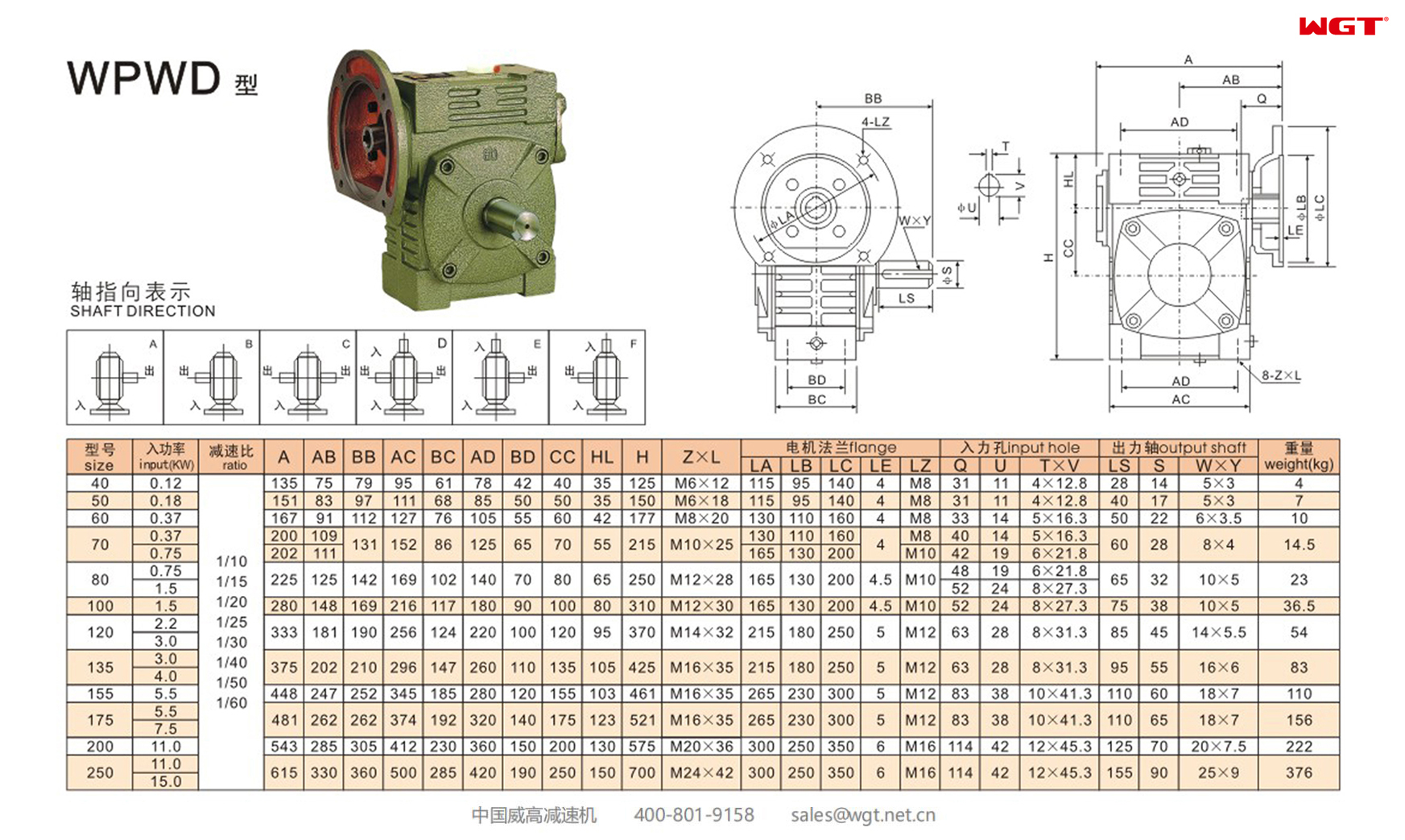
The WPWD175 worm gear reducer is the 175 mm centre-distance member of WGT Weigao Transmission's universal worm gearbox range, built in the WPWD execution: a one-piece housing with a right-hand single-start worm and an integral motor flange on the input side, so the drive motor bolts straight onto the reducer instead of being coupled through a separate bracket. That turns an ordinary worm gearbox into a compact, self-contained drive package for a narrow machine frame. Factory ratios run from 1/10 to 1/60 with 415 to 1450 N·m of rated output torque, so one casting covers slow augers, ribbon mixers, conveyors, hoists and packaging lines. For buyers working through gear reducer selection and gearbox sizing, the figures below are catalogue data for this exact model rather than generic family ranges.
The designation reads left to right: W is the product code for a worm gear speed reducer, P the whole one-piece box structure, the second W the universal box model, and D the input shaft with motor flange; the trailing number is the centre distance in millimetres. The WP family spans 40 mm to 250 mm centre distances, and because the housing is a universal box the same frame can be built with different shaft arrangements. The code also allows a two-stage build (E), a multi-stage build (EE), a hollow output shaft (K), and the housing arrangement letters A, S, O, X, T and V to orient the drive to the machine layout.
Typical Specifications of the WPWD175 Worm Gear Reducer
| Item |
Typical Range |
Notes |
| Type |
Single-stage universal worm gear reducer with integral motor flange |
WPWD execution: D = input shaft with motor flange; right-hand worm thread as standard |
| Centre distance |
175 mm |
One-piece box structure (P code); WP family spans 40 - 250 mm |
| Factory ratios |
1/10, 1/15, 1/20, 1/25, 1/30, 1/40, 1/50, 1/60 |
Eight catalogue ratios for this centre distance |
| Rated input power |
7.5 kW at 1/10 - 1/30; 5.5 kW at 1/40 - 1/60 |
Both values at an input speed of 1500 r/min |
| Output speed |
150 r/min at 1/10 down to 25 r/min at 1/60 |
n2 = n1 / i, with n1 = 1500 r/min |
| Rated output torque |
415 N·m at 1/10 rising to 1450 N·m at 1/60 |
Ratio-by-ratio figures listed in the table below |
| Output shaft |
Ø65 mm x 110 mm, 18 x 7 key |
Solid output shaft as standard; hollow shaft with the K code |
| Input bore |
Ø38 mm x 83 mm, 10 x 41.3 key |
Motor flange has four M12 holes on a 300 mm pitch circle |
| Motor flange |
LA 265 mm, LB 230 mm, LC 300 mm, LE 5 mm |
Flange thickness LE = 5 mm, fixing thread LZ = M12 |
| Housing dimensions |
A 481, AB 262, BB 262, AC 374, BC 192 mm |
Further frame refs: AD 320, BD 140, CC 175, HL 123, H 521 mm |
| Mounting feet / weight |
M16 x 35 mm feet; 156 kg |
Complete gearbox without motor |
| Input speed limit |
2000 r/min maximum, 600 - 1800 r/min typical |
Exceeding 2000 r/min overloads the bearings and shortens service life |
| Allowable oil temperature |
95 °C maximum |
Below this limit the unit may keep running if the temperature is no longer rising |
These are catalogue figures for the standard WPWD175 build. Final selection must be checked against the duty cycle, mounting arrangement and ambient temperature of the driven machine.
Rated Output Torque by Ratio
| Ratio |
Output speed at 1500 r/min input |
Rated input power |
Rated output torque |
| 1/10 |
150 r/min |
7.5 kW |
415 N·m |
| 1/15 |
100 r/min |
7.5 kW |
602 N·m |
| 1/20 |
75 r/min |
7.5 kW |
783 N·m |
| 1/25 |
60 r/min |
7.5 kW |
1002 N·m |
| 1/30 |
50 r/min |
7.5 kW |
1074 N·m |
| 1/40 |
37.5 r/min |
5.5 kW |
1008 N·m |
| 1/50 |
30 r/min |
5.5 kW |
1278 N·m |
| 1/60 |
25 r/min |
5.5 kW |
1450 N·m |
Torque figures are the maximum load a reducer of this size allows. Cross-check them against your own duty before committing to a model.
Where This Worm Gear Reducer Is Used
Screw and belt conveyors - slow auger shafts on bulk handling lines, where the 25 to 100 r/min output range sits mid-scale
Ribbon and paddle mixers - agitator drives that must start against a settled product load and so need a generous service factor
Hoists, winches and small cranes - compact lifting units where the integral motor flange saves the space a separate pedestal would take
Packaging machinery - metering screws, film pullers and carton erectors running at 37 to 75 r/min
Feeding and dosing equipment - volumetric feeders and dosing screws in food, chemical and pharmaceutical plant
Elevator and machine tool drives - bucket elevator head shafts, indexers, cams and reciprocating mechanisms
Selection Example: 7.5 kW Conveyor Drive at 50 r/min
A stainless steel trough conveyor on a food processing line runs at 50 r/min from a 7.5 kW motor at 1500 r/min, loaded by the trough chain and the material weight. The duty is continuous, roughly 16 hours per day, with frequent start-stop cycles.
Step 1 - ratio. i = n1 / n2 = 1500 / 50 = 30, so the catalogue ratio is 1/30, which gives an output speed of 1500 / 30 = 50 r/min, a rated output torque of 1074 N·m and an input rating of 7.5 kW.
Step 2 - working torque. Motor shaft torque at 1500 r/min is T = 9550 x P / n = 9550 x 7.5 / 1500 = 47.8 N·m. At an assumed 75% worm efficiency and a ratio of 30 the theoretical output torque is T1 = 47.8 x 30 x 0.75 = 1074 N·m, matching the catalogue figure for 1/30 exactly.
Step 3 - service factor. The reducer is sized for a continuous eight-hour day at steady load. For a conveyor running 10 - 24 hours per day under uniform load the running condition factor is K = 1.25, and because it starts and stops more than ten times per hour K is multiplied by a further 1.2, giving K = 1.50. The revised torque is T2 = T1 x K = 1074 x 1.50 = 1611 N·m.
Step 4 - frame size. 1611 N·m exceeds the 1074 N·m available at 1/30 on the WPWD175, so the 175 mm frame is not enough. The next centre distance up in the WPWD family, the 200 mm frame, carries 1680 N·m at 1/30, and 1611 N·m sits inside that figure with usable margin.
Step 5 - input power re-check. At 1/30 the high-power group applies, so the 200 mm unit accepts 11 kW, comfortably covering the 7.5 kW motor. The 175 mm unit would have been acceptable on power at 1/30 but fails on torque once the service factor is applied, and moving to the 1/40 - 1/60 group would drop the input rating to 5.5 kW, below the motor.
Step 6 - mechanical checks. The 200 mm frame carries an input bore of Ø38 x 83 mm with a 10 x 41.3 key that must match the motor shaft, and an output shaft of Ø65 x 110 mm with an 18 x 7 key that must clear the driven shaft and its hub. The 1500 r/min input speed is inside the 600 - 1800 r/min working band. Note that this model does not self-lock: if the driven machine can back-drive the motor, confirm backlash and holding behaviour with the manufacturer before relying on the reducer to hold position.
Installation, Lubrication and Maintenance
Fill the housing with oil up to the centre line of the oil gauge and remove the small screw in the air vent, otherwise the gearbox cannot start turning. Oil grade depends on ambient temperature: N220 to N320 for -30 °C to 40 °C, and N320 to N460 for 40 °C to 65 °C; for overseas duties the catalogue offers synthetic PG 220 and PG 460 and mineral ISO VG 200, 320, 460 and 680 grades, selected by worm shaft speed and shaft orientation. Change the oil after the first 100 hours of running, washing the interior out and refilling with fresh oil, then renew it every 2500 hours. Keep the sprocket wheel and gear close to the bearings to reduce bending stress on the hanging shaft, and grease the worm shaft input hole and keyway properly when assembling - over-tightening causes rusting after long service. If the motor weight is greater than the common unit, a supporting set is required.
Before commissioning, check the model, centre distance, ratio, input connection method, output shaft structure, shaft directions and rotation direction against the machine requirements. The worm thread hand sets the output rotation: with the standard right-hand thread and the shafts viewed as the catalogue photographs show, a clockwise input gives a counter-clockwise output on the WPA execution and a clockwise output on the WPS execution. If abnormal circumstances appear, stop and check the unit against the fault table in the manual.
Get the Exact Model Online — Free Selection System
To confirm the centre distance, ratio, torque rating and input power for your own duty cycle, use the WGT Motor & Gearbox Online Selection System. Enter the input speed, output speed, load and duty hours, and the system returns the matching gearbox type, rated torque and motor power together with the dimension and oil data needed for the drawing.