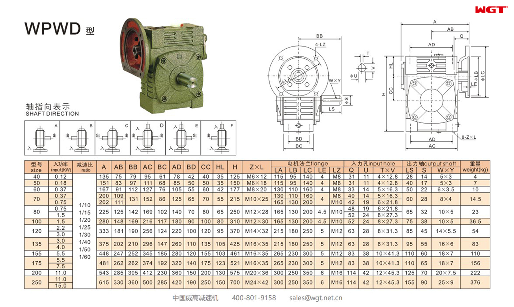
The WPWD155 worm gear reducer is the 155 mm centre-distance member of WGT Weigao Transmission's universal worm gearbox range, built in the WPWD execution: a one-piece housing with a right-hand single-start worm, and an integral motor flange on the input side so the drive motor bolts straight onto the reducer instead of being coupled to it through a separate bracket. That turns an ordinary worm gearbox into a compact, self-contained drive package that fits inside a narrow machine frame. The WPWD155 runs factory ratios from 1/10 to 1/60 and carries 305 to 1039 N·m of rated output torque, so one casting covers slow augers, ribbon mixers, conveyors, hoists and packaging lines. For buyers working through gear reducer selection and gearbox sizing, the figures below are catalogue data for this exact model rather than generic family ranges.
The model designation is read left to right: W is the product code for a worm gear speed reducer, P the whole one-piece box structure, the second W the universal box model, and D the input shaft with motor flange; the trailing number is the centre distance in millimetres. The WP family covers centre distances from 40 mm to 250 mm, and because the housing is a universal box the same frame can be built with different shaft arrangements, so a designer can orient the drive to suit the machine layout instead of relocating the gearbox. The full code also allows an optional two-stage build (E), a multi-stage build (EE), a hollow output shaft (K) and the housing arrangement letters A (input shaft below), S (input shaft above), O (output shaft upward), X (output shaft downward), T (input shaft upward) and V (input shaft downward) to be added to the basic WPWD form.
Typical Specifications of the WPWD155 Worm Gear Reducer
| Item | Typical Range | Notes |
| Type | Single-stage universal worm gear reducer with integral motor flange | WPWD execution: D = input shaft with motor flange; right-hand worm thread as standard |
| Centre distance | 155 mm | One-piece box structure (P code); WP family spans 40 - 250 mm |
| Factory ratios | 1/10, 1/15, 1/20, 1/25, 1/30, 1/40, 1/50, 1/60 | Eight catalogue ratios for this centre distance |
| Rated input power | 5.5 kW for ratios 1/10 - 1/30; 4.0 kW for ratios 1/40 - 1/60 | Rated at 1500 r/min input; catalogue torques are quoted at 1500 r/min |
| Rated output torque | 305 - 1039 N·m | 305 N·m at 1/10 rising to 1039 N·m at 1/60 |
| Output speed | 25 - 150 r/min | From 1500 r/min input: 150 / 100 / 75 / 60 / 50 / 37.5 / 30 / 25 r/min |
| Permitted input speed | Not above 2000 r/min; 600 - 1800 r/min normal | Excessive input speed shortens bearing life |
| Motor flange | LA 265 mm, LB 230 mm, LC 300 mm, LE 5 mm, LZ M12 | Catalogue flange dimensions; M12 fixing on the LC pitch circle |
| Input bore | Ø38 × 83 mm, key 10 × 41.3 mm | Catalogue codes Q / U / T×V |
| Output shaft | Ø60 × 110 mm, key 18 × 7 mm | Catalogue codes S / LS / W×Y |
| Envelope | 448 (A) × 345 (AC) × 461 mm high (H) | Housing 252 mm wide (BB); foot mounting M16 × 35 (Z×L) |
| Mass | 110 kg | Reducer only, excluding the drive motor |
Table shows the WPWD155 catalogue data. Torque and power are catalogue values at 1500 r/min input; every installation must still be verified against its own duty cycle, and the reducer oil temperature limit is 95 °C.
Rated Output Torque and Output Speed of the WPWD155 by Ratio
| Ratio i | Output speed at 1500 r/min | Rated input power | Rated output torque | Catalogued efficiency range |
| 1/10 | 150 r/min | 5.5 kW | 305 N·m | 77 - 90 % |
| 1/15 | 100 r/min | 5.5 kW | 411 N·m | 76 - 88 % |
| 1/20 | 75 r/min | 5.5 kW | 525 N·m | 75 - 84 % |
| 1/25 | 60 r/min | 5.5 kW | 709 N·m | 72 - 82 % |
| 1/30 | 50 r/min | 5.5 kW | 760 N·m | 68 - 82 % |
| 1/40 | 37.5 r/min | 4.0 kW | 713 N·m | 64 - 75 % |
| 1/50 | 30 r/min | 4.0 kW | 853 N·m | 62 - 72 % |
| 1/60 | 25 r/min | 4.0 kW | 1039 N·m | 60 - 71 % |
Torque figures are the maximum load the catalogue allows for this frame at the stated ratio and input speed. Efficiency falls as the ratio rises, which is why the high-ratio builds are rated at 4.0 kW while the low-ratio builds take the full 5.5 kW. The efficiency ranges are the values published for the worm gear reducer family as a whole, so the exact figure for a given build should be taken from the order confirmation.
Where This Universal Worm Gear Reducer Is Used
- Conveyor and auger drives: belt, roller, chain and screw conveyors running at 25 - 75 r/min, where the integral motor flange removes the separate motor bracket and the whole drive drops into a narrow machine frame.
- Feed and dosing equipment: batching-plant augers, screw feeders and volumetric dosers at 50 - 100 r/min, holding speed steady against a fluctuating product load.
- Mixers and agitators: ribbon and paddle mixers, dissolvers and sludge stirrers that run 10 to 24 hours a day and therefore sit in the higher service-factor columns of the selection table.
- Packaging and printing machinery: wrapping, labelling, carton sealing, collating and paper-feeding drives at 60 - 150 r/min, where a keyed output shaft and a compact gearmotor layout are both wanted.
- Hoists, lifts and material handling: small trolleys, chain hoists, vertical screw conveyors and bucket elevators, where the 305 - 1039 N·m torque band covers light to medium lifting duty.
- Fans, blowers and ventilation equipment: centrifugal fan drives at 25 - 100 r/min, with the reducer mounted directly on the fan inlet or coupled to the fan shaft.
Selection Example: 5.5 kW Drive for a 50 r/min Paddle Agitator
A mixing vessel needs its paddle agitator driven at 50 r/min by a 5.5 kW, 1500 r/min motor. The machine runs a uniform load for eight hours a day and is stopped and started roughly six times per hour.
Step 1 - Ratio. i = 1500 / 50 = 30, so the catalogue ratio is 1/30. The 1500 r/min input sits inside the recommended 600 - 1800 r/min band and well below the 2000 r/min ceiling, so the worm set is not being over-speeded.
Step 2 - Theoretical output torque. The input torque is T = 9550 × P / n = 9550 × 5.5 / 1500 = 35.0 N·m. Passing through the worm set at 1/30 gives T1 = 35.0 × 30 × η = 35.0 × 30 × 0.724 = 760 N·m. The implied efficiency of 72.4 % sits inside the published 68 - 82 % band for 1/30, and 760 N·m is exactly the catalogue rating of the WPWD155 at this ratio, which confirms that this frame is the right size for the duty at nominal load.
Step 3 - Service factor. For a uniform load at 6 - 10 hours per day the catalogue running condition factor K is 1.00 (uniform load 0.80 / 0.90 / 1.00 / 1.25 for 0.5-2, 2-6, 6-10 and 10-24 hours per day; medium shock 0.90 / 1.00 / 1.25 / 1.50; heavy shock 1.00 / 1.25 / 1.50 / 1.75). The agitator is stopped and restarted about six times per hour, which is below the ten-starts-per-hour threshold, so no additional factor applies and K stays at 1.00.
Step 4 - Revised torque and catalogue check. T2 = T1 × K = 760 × 1.00 = 760 N·m. At 1/30 the WPWD155 is rated 760 N·m, so the unit passes, but only with zero margin - a result that tells you the frame is exactly matched rather than generously sized. The next size down, the WPWD135, is rated 565 N·m at 1/30 and would fail outright, which is why 155 mm is the correct frame here rather than a smaller box with a bigger motor.
Step 5 - Motor power confirmation. Working backwards with the catalogue efficiency for 1/30, P = T2 × n2 / (9549 × η) = 760 × 50 / (9549 × 0.724) = 5.50 kW, so the 5.5 kW motor is correctly matched to the 5.5 kW input rating of this build. If the same motor were instead used at 1/40 (37.5 r/min), the required input power would be 713 × 37.5 / (9549 × 0.70) = 4.01 kW, which matches the 4.0 kW rating of the high-ratio group - the second reason the same motor covers both duties.
Step 6 - Check the other side of the duty. If the product load later becomes fluctuating or shock-like, the medium-shock factor K becomes 1.25 and the revised torque rises to 950 N·m, which is more than the 760 N·m of the WPWD155 at 1/30; the frame then steps up to the WPWD175, rated 1074 N·m at 1/30. Drive speed, duty hours and shock class all move this answer, which is why the calculation is repeated rather than assumed - and why the selection system below is faster than working from the catalogue by hand.
Installation, Lubrication and Maintenance Notes
Mount the reducer on a flat, rigid base plate with the foot bolts tightened and shock-proofed, and align the prime mover, reducer and driven machine so the three shaft lines are coaxial. Input shaft extensions are machined to J6 and output shaft extensions to JS6, so couplings, pulleys and sprockets must be bored to a matching tolerance - too tight and the bearings are damaged, too loose and the power transmission suffers. Sprockets and gears should sit close to the bearings to limit shaft bending, and when bolting a motor to the WPWD input flange, grease the bore wall and keyway of the worm shaft to avoid a tight fit and subsequent rusting; if the motor is heavier than usual, provide a separate support. Output rotation follows the right-hand worm thread: on the WPA arrangement, facing the input and output shafts, an input turning clockwise gives a clockwise output, while on the WPS arrangement the output turns anticlockwise. All of these points belong in any gearbox maintenance schedule, because the oil condition, the grease on the worm shaft bore and the shaft alignment are what decide whether the unit keeps running for ten years or one.
Fill the housing with N220 to N320 oil for ambient temperatures of -30 to 40 °C, or N320 to N460 for 40 to 65 °C, up to the centre line of the oil gauge, and remove the small cone plug from the breather before starting. The catalogue also lists ISO VG 200, 320, 460 and 680 mineral oils, synthetic PG 220 and PG 460 grades and AGMA equivalents from 5 to 8EP. Flush and refill after the first 100 hours, then change the oil every 2500 hours; oil temperature may reach 95 °C provided it is not still rising. Typical faults have simple causes: overheating from improper connection between prime mover, reducer and driven machine, from overloading, from oil seal friction, from too much or too little oil, or from oil contaminated with impurities; vibration from a loosely mounted base plate, from a worn worm gear tooth surface, from worn bearings or from a loose set screw; noise from damaged bearings, poor tooth contact, insufficient lubricant or a foreign object inside the housing; and oil leakage from a damaged oil seal. Where the load overhauls the drive, confirm back-drive behaviour for the selected ratio before ordering, because the WP series is not published with a lead-angle table.
Get the Exact Model Online — Free Selection System
Open the WGT Motor & Gearbox Online Selection System, enter your power, input speed, required output speed or ratio, plus the torque and duty of the driven machine, and the system returns the matching reducer size, ratio and rating with the full technical data. It removes the arithmetic and the judgement calls from service factor gearbox work and is the fastest route to a firm quotation for a worm gear reducer maintenance spare or a new drive. To cross-reference against SEW, NORD, Flender or a Chinese equivalent, send us the nameplate photo or type designation and our engineers will reply with the cross-reference, price and lead time.